Beschreibung
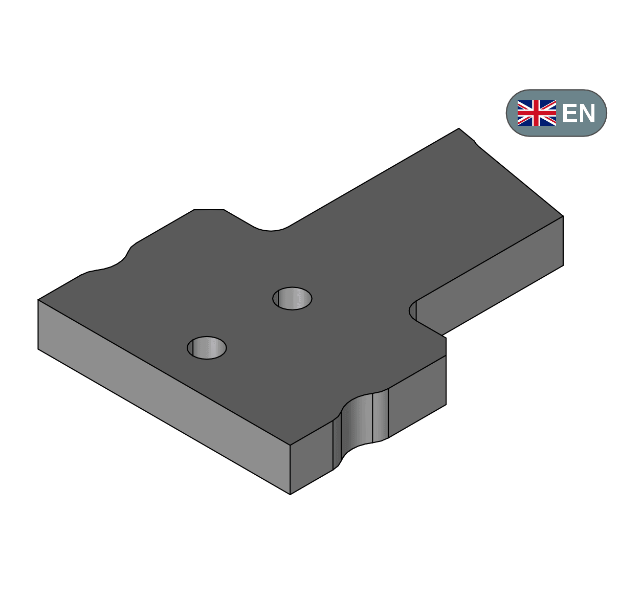
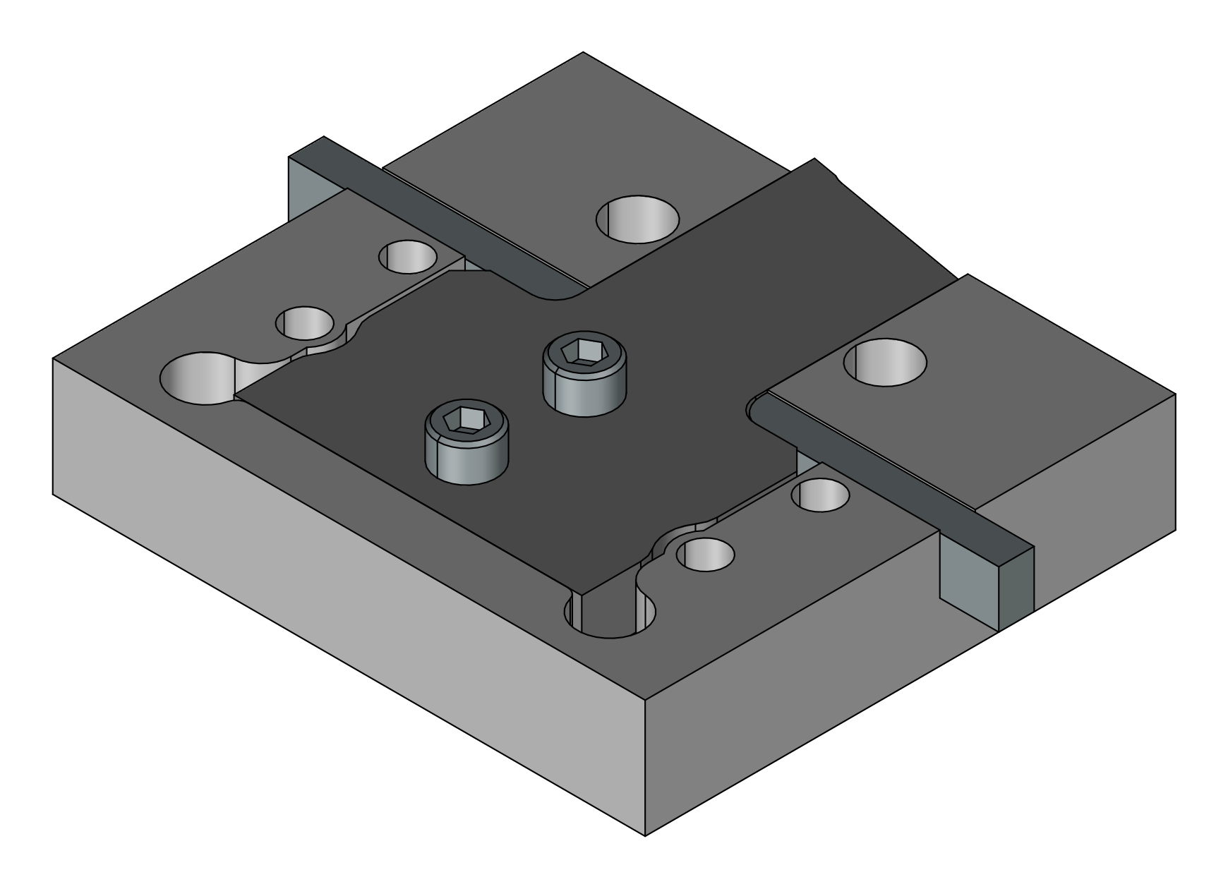
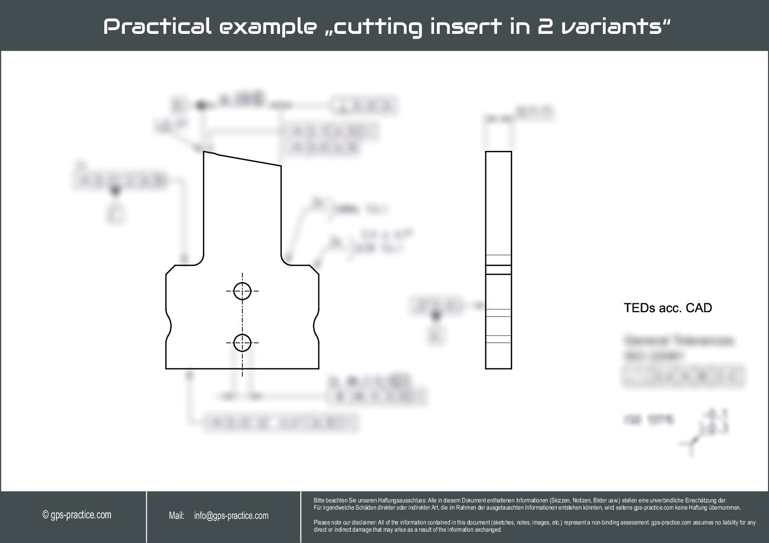
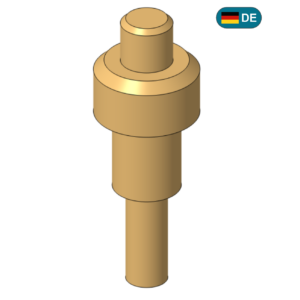
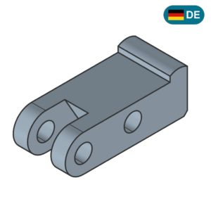
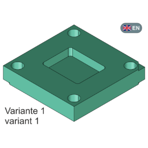
In this application example, a cutting insert is specified, which is assembled in a holding insert. A guiding area (joining / assemblability) must be described, as well as a typical installation situation (stop/locking). Through-holes are intended to allow the cutting insert to be fixed in place. The orientation and position of the cutting edge must be complete and unambiguously defined. Areas that are less relevant for the function are described completely and clearly using general geometrical tolerancing.
Length of explanation video (Step by Step guide) : Approx. 30 min.
Difficulty Level:
variant 1: Suitability 2-3 | variant 2: Suitability 2-3
Description of the level of difficulty (suitability for the user):
1 – The user has basic knowledge but has not yet used ISO GPS frequently in practice and takes first steps.
2 – The user has basic knowledge but is not proof about using ISO GPS and would like to gain more general confidence.
More „special“ or complex modifiers (these are usually listed in the example description) are applied selectively.
3 – The user has sufficient knowledge, can already use frequently used ISO GPS tools without difficulty,
and would like to deepen knowledge selectively based on typical functional descriptions,
which is usually also product-specific (e.g., snapping features (latching hooks) on a plastic injection-molded part, special demand hole patterns, i.e. multi-level patterns etc.)
used in the example (i.e., listed in the description) (e.g., direction only or certain combinations of dimensional tolerancing, as well as SIM or similar modifications).
4 – The user has extensive knowledge, has been working with ISO GPS for a long time,
and would like to learn about very specific applications or modification operations, which usually describe more complex functional requirements and products.
This requires, for example, situation features, reference elements, filter information, association modifiers etc.