Beschreibung
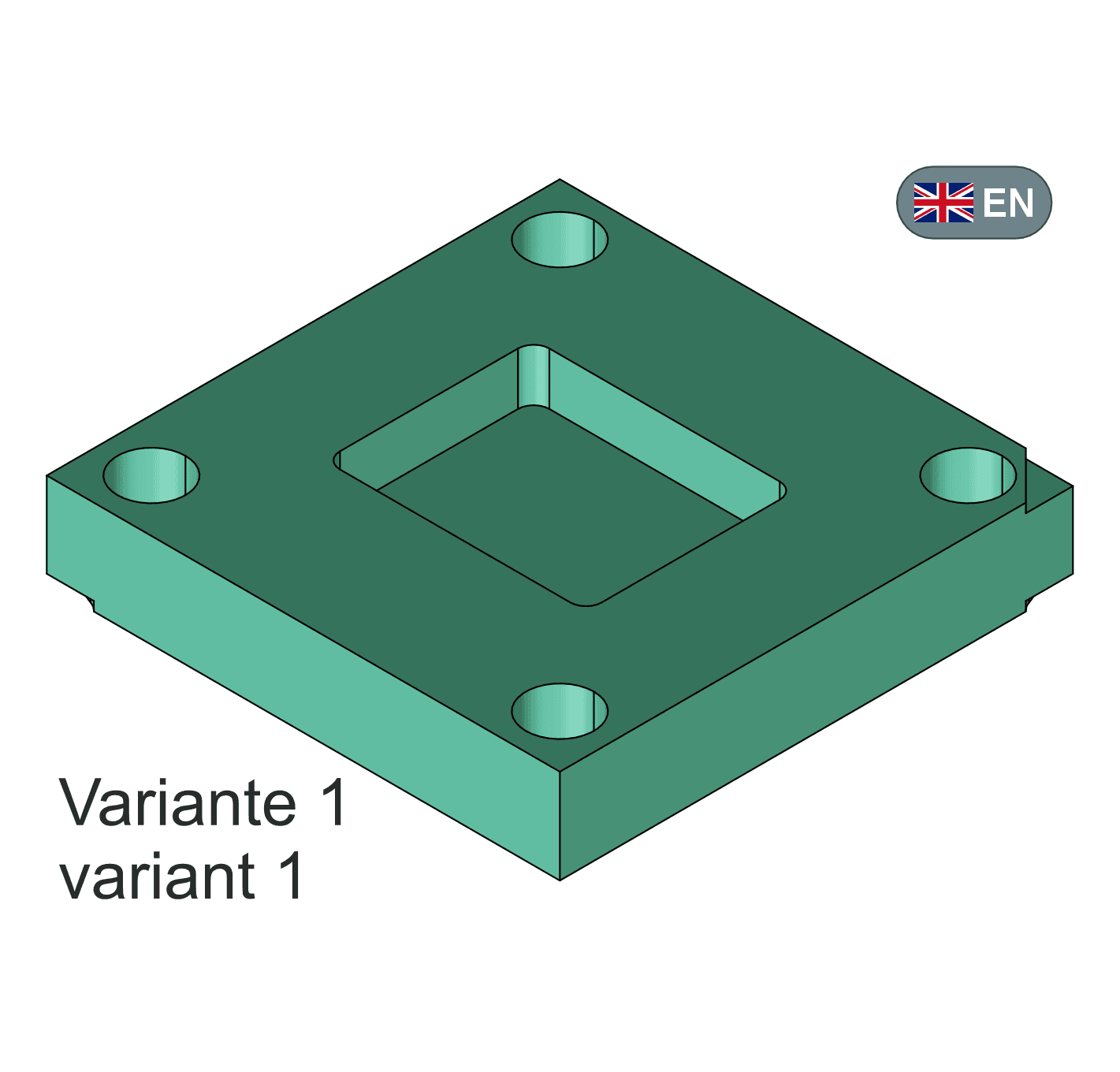
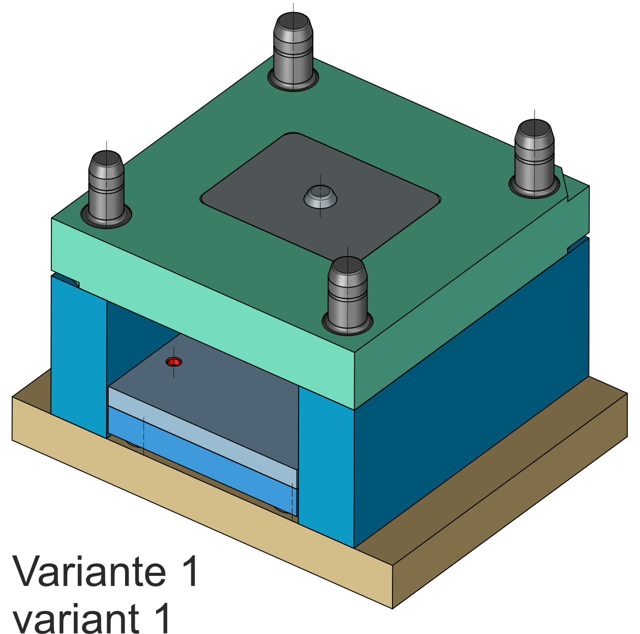
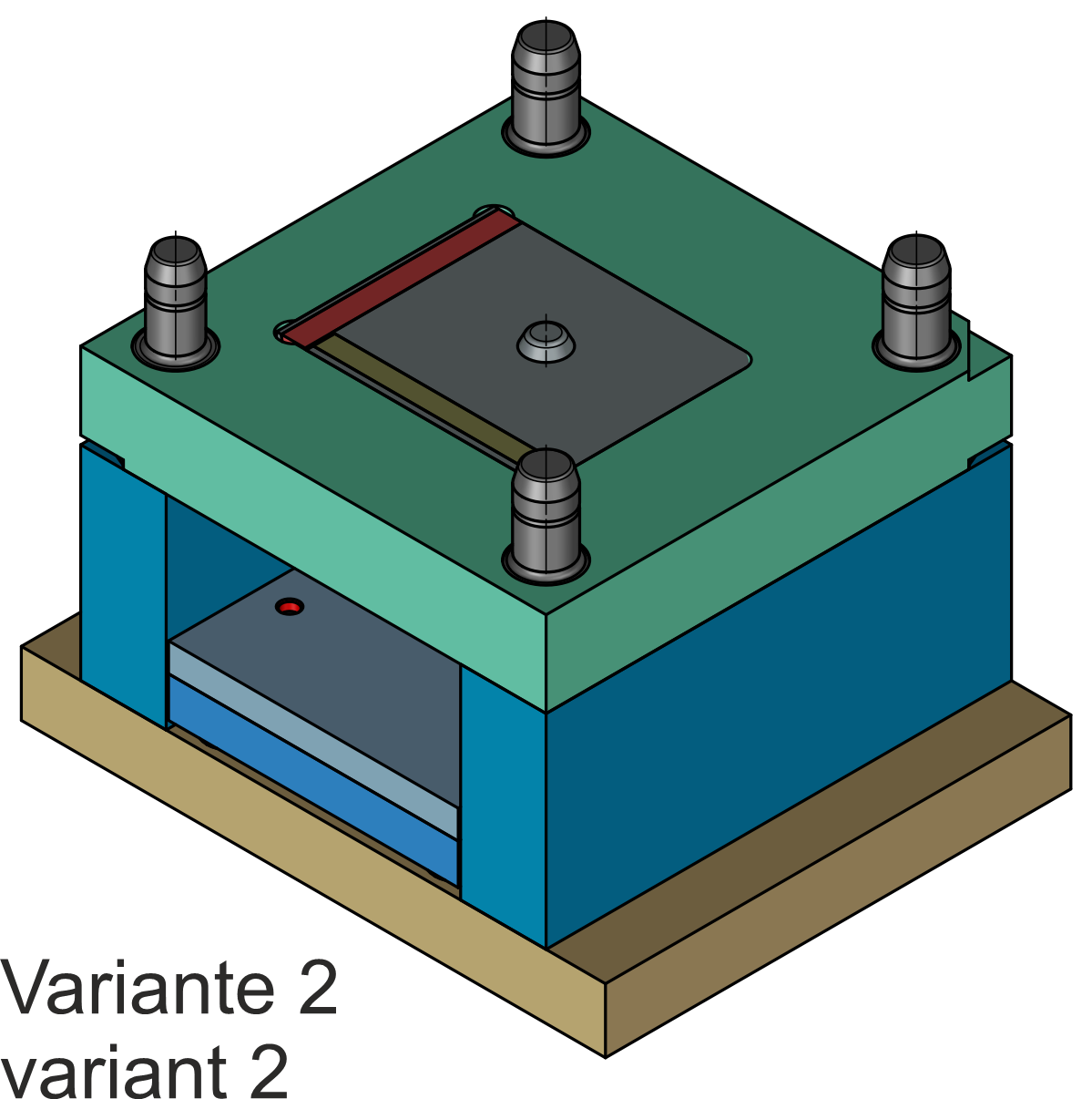
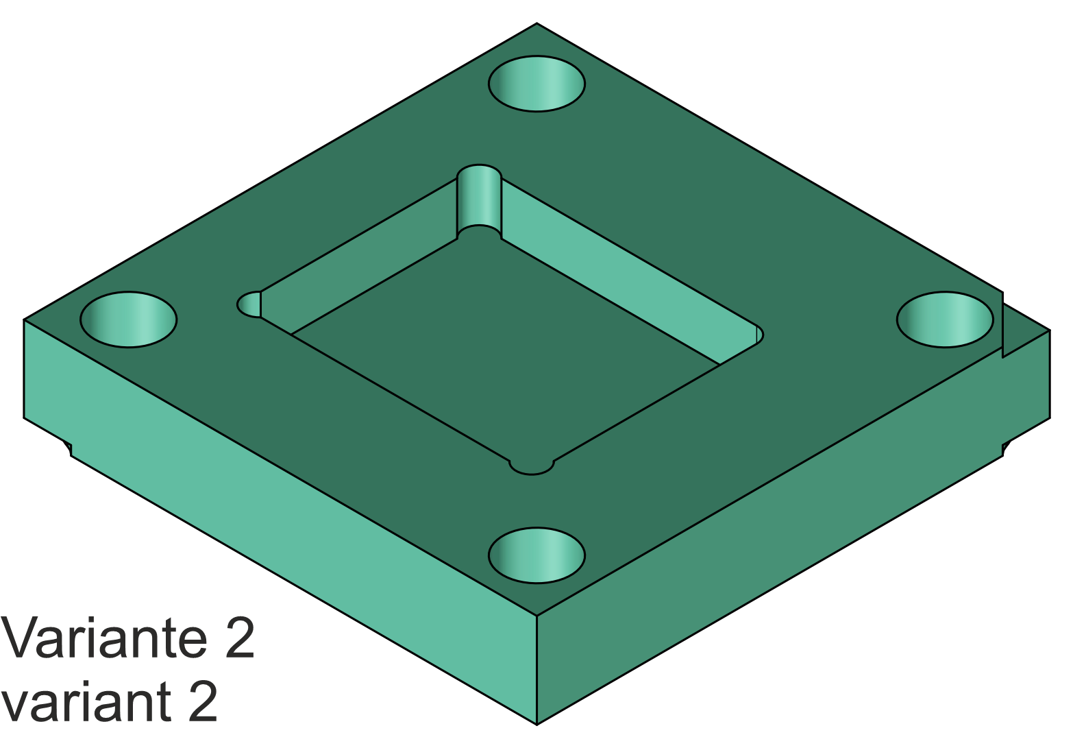
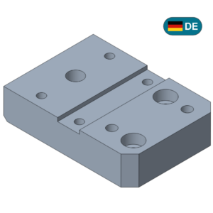
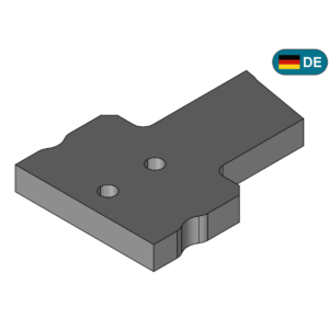
This is about the basic structure of a mold plate, such as those used in mold making (plastic injection molding).
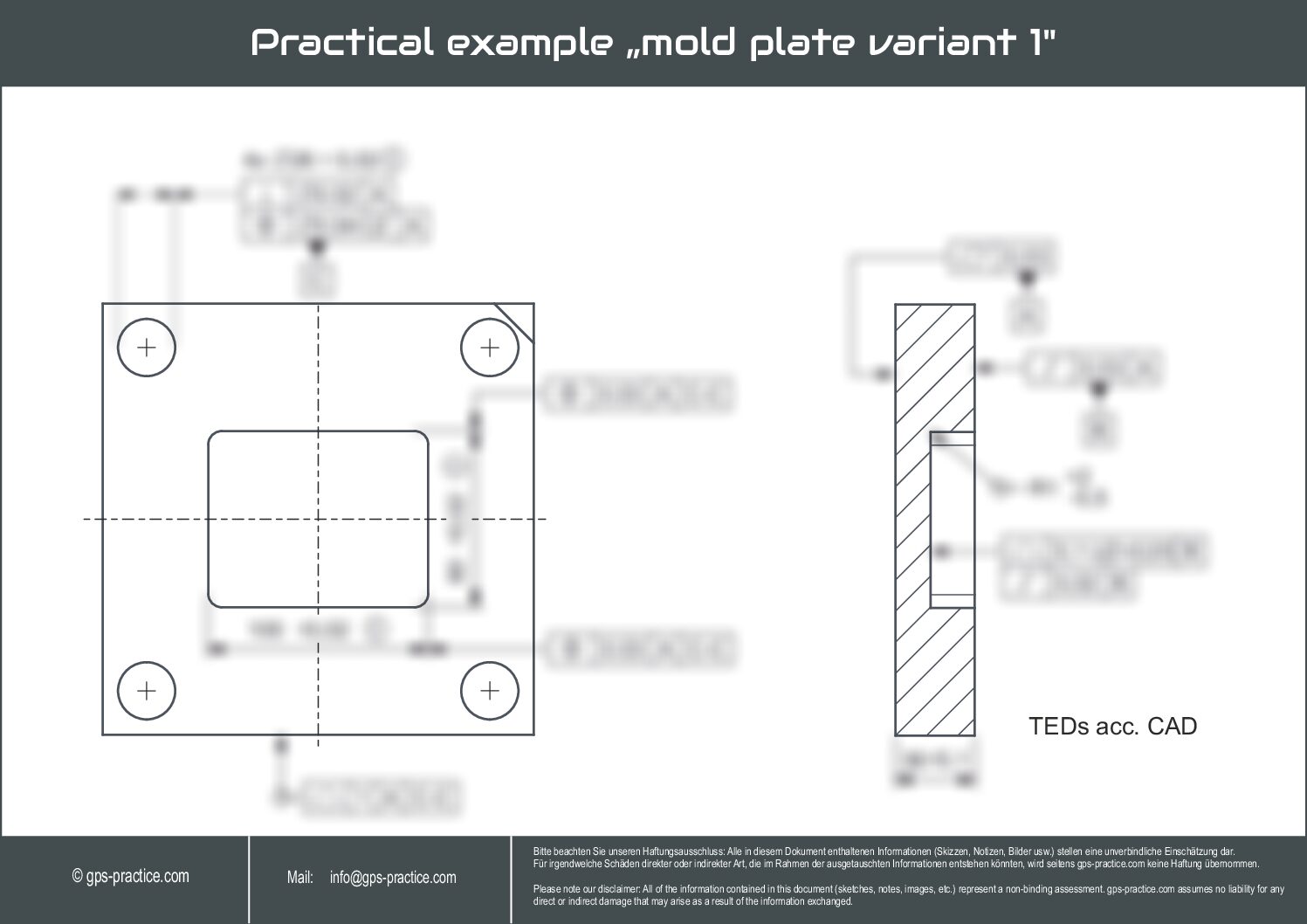
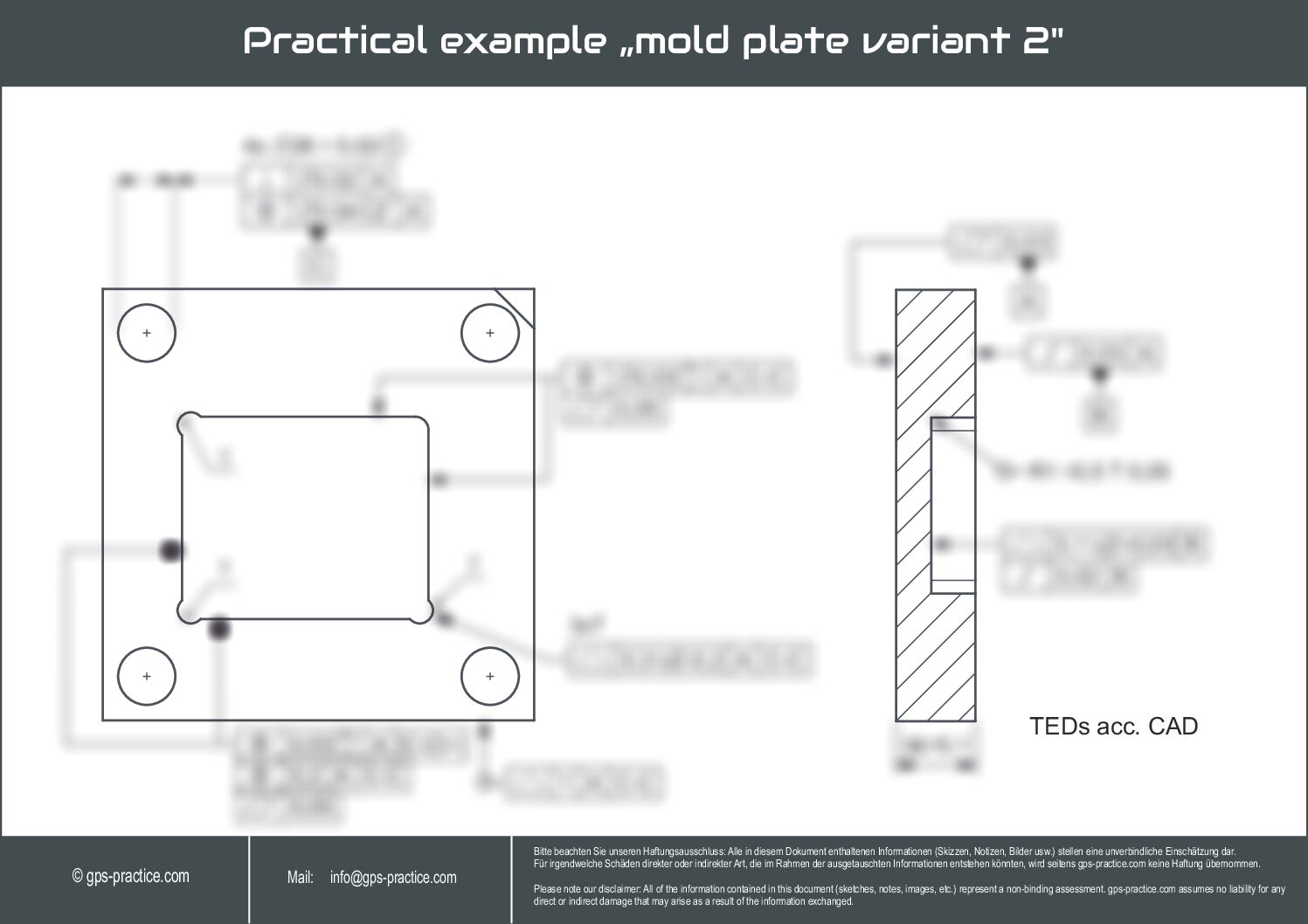
The tolerances of the mold cavity are determined on two different (functional) variants.
Other funtional elements required in practice (e.g., screw holes) were omitted for the sake of simplicity. Drilling patterns, etc., are discussed more in detail in further videos.
Length of explanation video (Step by Step guide) : Approx. 46 min.
Difficulty Level:
variant 1: Suitability 1-2 | variant 2: Suitability 2-3
Description of the level of difficulty (suitability for the user):
1 – The user has basic knowledge but has not yet used ISO GPS frequently in practice and takes first steps.
2 – The user has basic knowledge but is not proof about using ISO GPS and would like to gain more general confidence.
More „special“ or complex modifiers (these are usually listed in the example description) are applied selectively.
3 – The user has sufficient knowledge, can already use frequently used ISO GPS tools without difficulty,
and would like to deepen knowledge selectively based on typical functional descriptions,
which is usually also product-specific (e.g., snapping features (latching hooks) on a plastic injection-molded part, special demand hole patterns, i.e. multi-level patterns etc.)
used in the example (i.e., listed in the description) (e.g., direction only or certain combinations of dimensional tolerancing, as well as SIM or similar modifications).
4 – The user has extensive knowledge, has been working with ISO GPS for a long time,
and would like to learn about very specific applications or modification operations, which usually describe more complex functional requirements and products.
This requires, for example, situation features, reference elements, filter information, association modifiers etc.